
BlackCoat journal
By BlackCoat Services
6 min read
Can a 3D scan recreate a replacement part?
A scan can capture useful reference geometry, but recreating a replacement part often needs measurements, CAD reconstruction and a review of how the part must work.
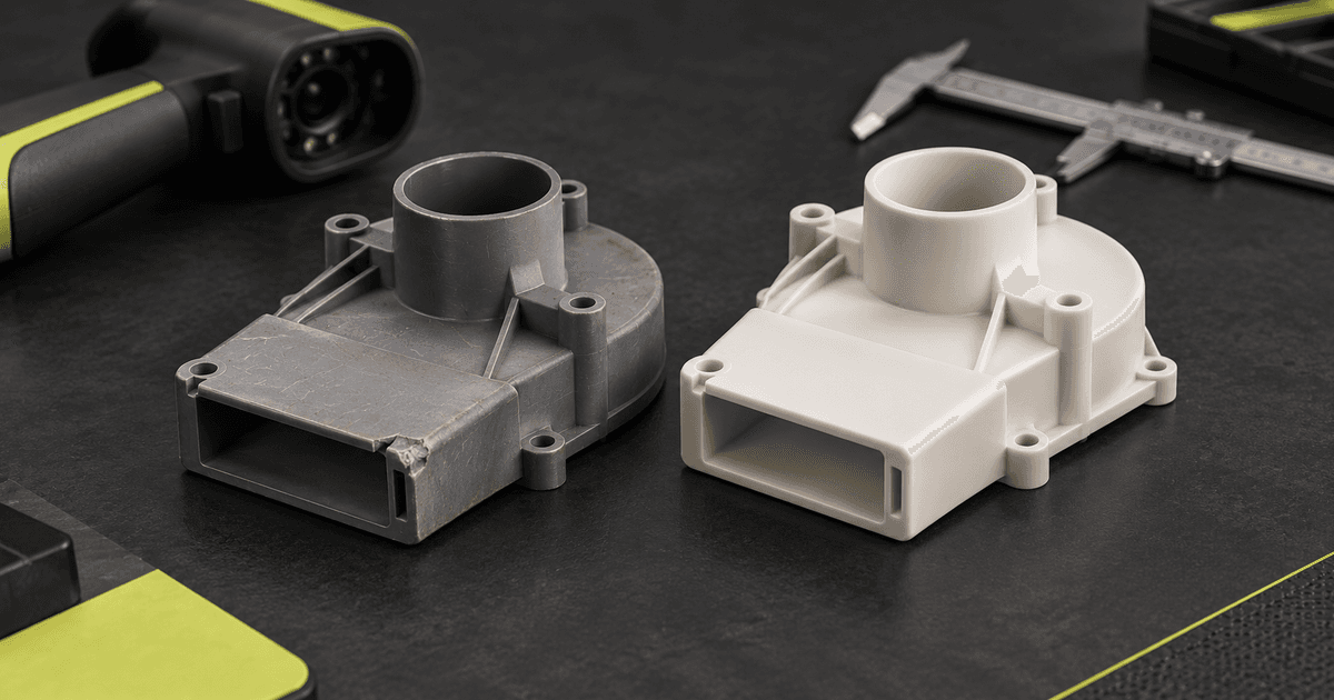
A 3D scan can help recreate a replacement part, but it does not automatically recover the original design or produce a manufacturing-ready CAD model. The workflow may combine scanning, direct measurement, CAD reconstruction and a review of how the replacement must fit and work.
The first question is not simply whether an object can be scanned. It is which information must be recovered. A project that needs the outside form of a cover is different from one that depends on a bearing seat, fastening pattern, hidden channel or controlled fit with another component.
What a 3D scan actually captures
A scanner records points from surfaces it can observe under the chosen setup. Processing can align separate views and represent the captured surface as a point cloud or polygon mesh. That data can document freeform shapes and provide a reference for comparison, measurement or further modelling.
The result represents the physical object as presented, including wear, distortion, damage, manufacturing variation and previous repairs. Those details may be important evidence, but they are not necessarily features that should be copied into a replacement.
Why a scan is not automatically editable CAD
A scan mesh describes a surface using many small connected faces. An editable engineering model usually describes intentional features such as planes, cylinders, holes, wall sections and relationships between dimensions. Converting the captured surface into useful CAD can therefore involve identifying features, fitting reference geometry and rebuilding the part around its functional intent.
Some projects can use a cleaned mesh directly for a limited purpose. Others need a controlled solid model that can be revised, dimensioned or adapted. The required output should be agreed before capture because an archive mesh, a visual model and production-focused CAD serve different needs.
Hidden geometry still needs another source
A surface that cannot be seen by the scanner cannot be inferred reliably from the visible exterior. Deep recesses, enclosed channels, assembled interfaces and internal features may require disassembly, another viewing angle, direct measurement, drawings or design assumptions agreed with the owner.
Access and surface condition also affect the capture plan. Gloss, transparency, very dark areas, dirt and damaged edges can require preparation or a different method. These conditions should be identified during review rather than hidden behind a general promise that every object can be scanned in the same way.
Separate wear from design intent
An old component may no longer represent its original geometry. A hole may have enlarged, a face may have bowed, an edge may have chipped or a previous repair may have changed the shape. Reproducing those conditions exactly can preserve the problem rather than solve it.
Explain why the original part is being replaced and identify undamaged references where possible. Symmetry, mating components, known fasteners, drawings and measurements can help distinguish intended features from wear. Any reconstructed feature should remain an explicit design decision, not an invisible correction.
When direct measurement may be more useful
Scanning is especially useful for complex contours and freeform surfaces, but simple functional geometry may be clearer to measure directly. A plate defined by overall size, hole positions and thickness may not benefit from a dense surface mesh. Many replacement projects use both approaches: scanning for overall form and measurement for critical interfaces.
A practical scan-to-part workflow
- Define the replacement's intended use, interfaces and acceptance points.
- Inspect the physical part for access, surface condition, wear and damage.
- Choose which areas need scanning and which need direct measurement or another reference.
- Capture and process the visible geometry into an aligned reference mesh.
- Reconstruct or adapt the required CAD features without silently copying defects.
- Review the CAD against scan data, measurements and mating components.
- Select a production route only after the geometry and working requirements are understood.
- Use an agreed prototype or first part to check the specific fit and function questions that matter.
A printable shape is not always a suitable replacement
Producing a closed digital model does not establish that 3D printing is the right manufacturing route. The replacement's loads, environment, failure consequences, material needs, quantity, finish and interfaces still require review. Another process may be more appropriate, or printing may be useful for a prototype before a different production decision is made.
Take additional care where failure could affect safety, regulated equipment or essential operations. A geometry-capture workflow does not replace the engineering assessment, permissions, testing or compliance work that the application may require.
Send the physical part's details alongside its intended use, critical interfaces and available references. That helps identify where scanning will add information and which features need CAD work before the next decision.
Next steps