
BlackCoat journal
By BlackCoat Services
8 min read
Testing a functional 3D-printed part before ordering a batch
Use a prototype to check loads, fit, material behaviour and finishing. Record what the trial proves before repeating the part.
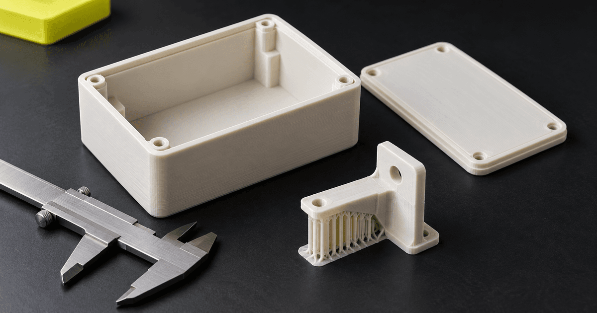
Before ordering repeat parts, use a prototype to answer a specific question about the design. It might need to locate a component, hold a load, flex repeatedly or stay clear of a moving mechanism. Define what counts as a pass and test a representative sample in its agreed finished state. A print that looks clean or fits once does not establish its strength or working life.
This guide concerns FDM, or fused deposition modelling, which builds parts from layers of plastic filament. It brings together design guidance and published demonstrations, with illustrations to explain the geometry. The illustrations and cited examples are not BlackCoat test results or production specifications.
Write down what the prototype must prove
Describe the job before choosing the mechanism or material. A bracket may need to hold an existing component without obstructing its cables. A lid may need to open by hand and stay attached during handling. Those descriptions give the trial something to check. A request for a stronger or more accurate print leaves the acceptance question unanswered.
- Identify what the part must hold, locate, protect or connect.
- Mark where forces act, including tightening and assembly loads.
- Describe the temperature, moisture and other service conditions.
- State whether the part must move or flex, and how often.
- Identify failure consequences and requirements that need specialist validation.
Jeremy Fielding's design-process explanation gives a useful starting point: define the outcome and constraints before committing to a preferred tool. A standard pin or a simpler fastening arrangement may solve the problem without adding a more complicated printed feature.
Check load direction before adding infill
FDM parts have direction-dependent mechanical behaviour because they are made from deposited paths and joined layers. A narrow upright peg loaded sideways may fail near its root. Changing orientation, shortening the projection or broadening its connection may deserve a trial before increasing infill, the printed structure inside the outer walls, across the whole part.
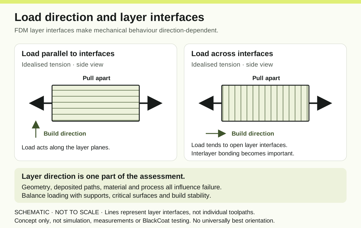
For bending, material farther from the neutral axis can contribute strongly to stiffness. The neutral axis is the line separating the stretched and compressed regions of the section. Outer walls, a larger section or local reinforcement may therefore be useful, but infill also supports surfaces and transfers loads. Compare changes against the actual failure mode rather than treating one infill percentage as a strength specification.
Keep the property you are testing clear. Stiffness describes resistance to deformation; strength concerns failure under a specified load. Toughness concerns energy absorbed before fracture. Fatigue concerns damage from repeated loading; creep is deformation over time under sustained load. A sample that is difficult to bend by hand does not prove all of those properties.
Test the interface against the real mating component
Clearance is the space designed between mating surfaces. Tolerance is the permitted dimensional variation. Compliance is deliberate flexibility that accommodates movement or variation. A locating shoulder and a flexible retaining tab can serve different purposes within the same joint; making every contact surface tight may simply make assembly difficult.
For a centred round peg, a hole diameter of 10.4 mm and a peg diameter of 10.0 mm leave 0.4 mm diametral clearance, equivalent to 0.2 mm on each side. This is an arithmetic example, not a recommended fit. Specify whether an allowance applies to the diameter, one side or the overall width of a feature.
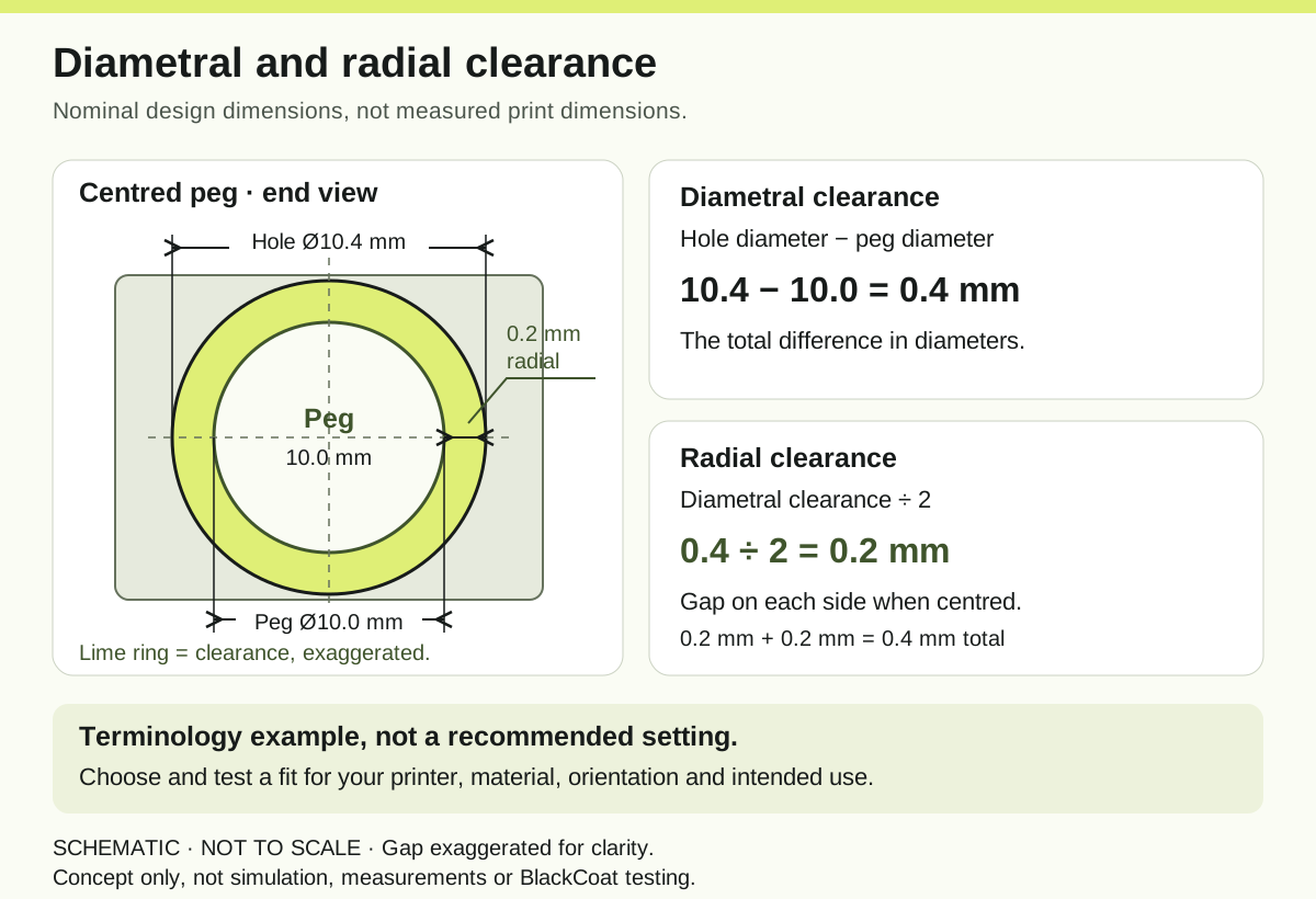
A small test section can help if it retains the wall behaviour, orientation, support conditions and finish that influence the final interface. Check it against the actual component. Record insertion, removal, unwanted movement and what changes after repeated assembly. The existing fit guide below covers locating faces, first-layer edges and other common causes of binding.
Include supports and first-layer geometry in the trial
An interface can bind because of a local roof defect rather than an undersized opening everywhere. Increasing the whole diameter may create extra play without fixing the sagging region. A teardrop roof, a different orientation or controlled support placement can be worth comparing, provided the change preserves the functional contact surfaces.
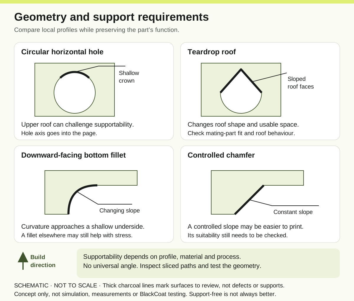
Hydra Research's guide shows a related example: staged bridges provide a foundation where a small hole begins above a larger recess. The stages depend on the intended layer height. A slicer prepares a model's printing paths. Inspect the resulting sequence in that software before adapting it to another profile; the drawing is not a dimension-independent recipe.
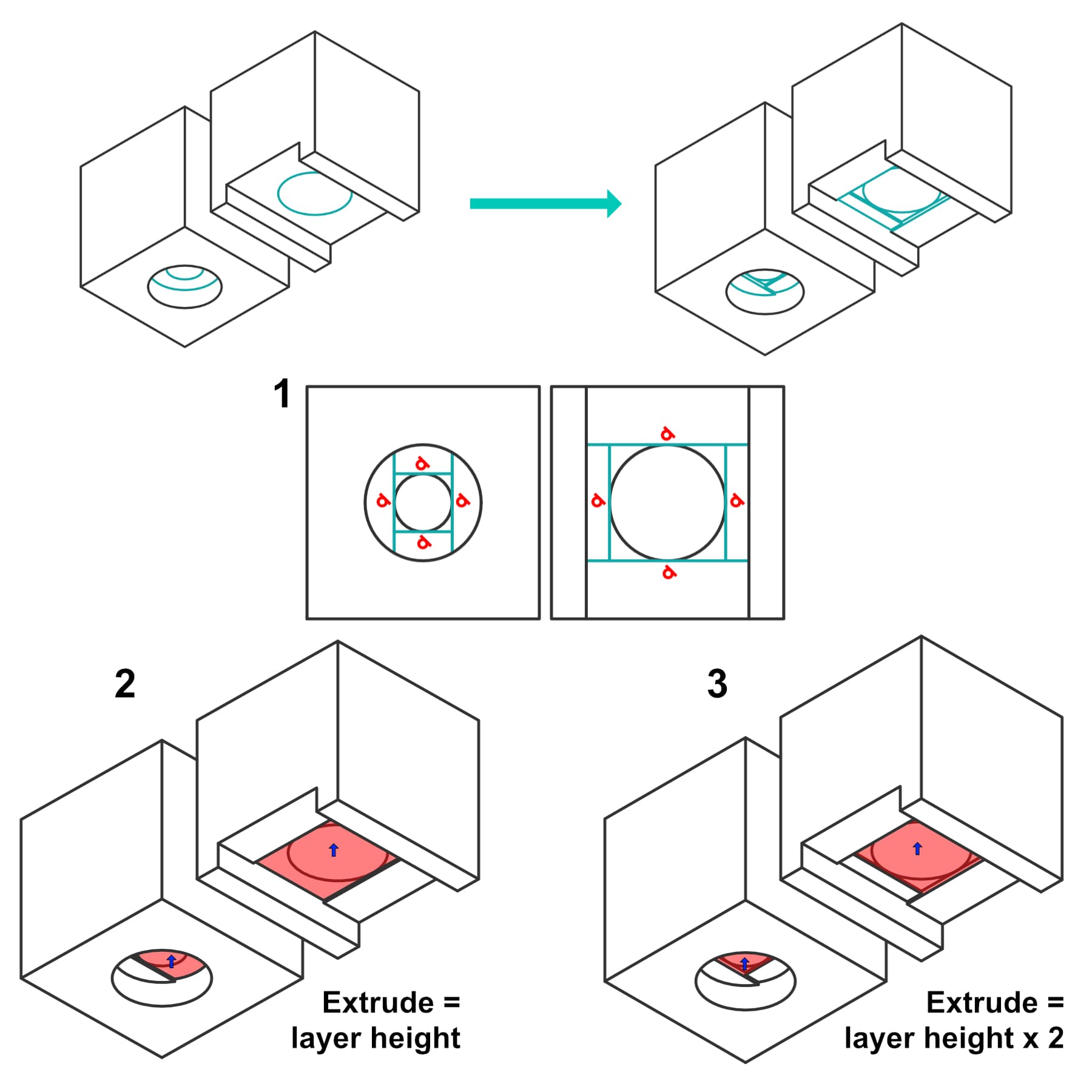
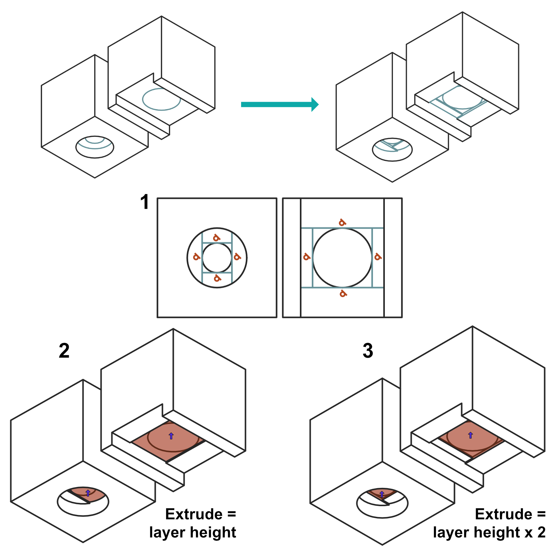
Also check what happens at the build plate. A widened first-layer edge can obstruct a fit. Rounded corners or local adhesion discs, often called mouse ears or lily pads, may help particular lifting corners, but they do not resolve every source of warping. Retain enough contact for stability and include any support or brim removal in the finished-sample inspection.
Match the test to the material and service conditions
Use the actual material grade and supplier's guidance when planning a trial. A clip under constant strain, a decorative enclosure and a fixture exposed to heat need different checks. Flexibility during installation is not evidence that a joint will retain the same force indefinitely. Record the environment and include sustained or repeated loading where the use requires it.
Reinforcement also needs a load path. Chopped-fibre filament, a separate continuous carbon rod and a laminated composite have different structures and interfaces. A rod that is loose in a cavity may not take the intended load. Likewise, a heat-resistant outer skin does not establish that a lower-temperature core or their interface will remain functional.
Review the sliced paths and record the settings
The CAD file describes the geometry; the slicer determines the paths used to make it. Check that small features survive, flexible parts remain separated and important regions have the intended structure. A narrow cut intended to create extra walls may be ignored, repaired away or left as a real separation. Keep the process profile with the trial rather than assuming the model alone records those choices.
Layer height also changes what the trial represents. Fine layers can reduce stair-stepping on shallow curves, while variable layers can reserve that detail for selected regions. Fewer layers do not guarantee a proportionally shorter print if extrusion flow limits the speed. Match the prototype's preparation to the question being tested.
Change the relevant feature and compare the result
- Write a prediction, such as a rod binding because of roof sag rather than the entire bore being too small.
- Keep a baseline, record its geometry and mass, and identify the feature or process variable being changed.
- Use a representative sample, with the material, orientation and finish recorded.
- Compare the results under consistent conditions and record where contact, deformation or failure occurs.
- Retest the chosen revision before treating it as the reference for repeat work.
A complete print is evidence that the build finished. A successful fit trial answers the assembly question it was designed for. Neither alone proves a safe load, wear life or suitability for another environment. Food-contact, electrical, pressure-containing, rotating and other safety-critical uses need appropriate assessment beyond this general prototype checklist.
For a BlackCoat enquiry, send the current file or sketch and explain what needs checking. Identify the actual interfaces, intended loads, environment and quantity. CAD support and an agreed prototype scope can then be discussed before the production route is confirmed.
Further reading
- Review the design before production
- Why printed parts do not always fit together
- Choose a material around the intended use
- Hydra Research: illustrated FFF design rules
- Protolabs Network: FDM build direction, holes and supports
- Protolabs Network: snap-fit clearances, creep and fatigue
- Ahn et al.: anisotropic properties of FDM ABS (research reference)
- Jeremy Fielding: defining a design problem
- JanTec Engineering: CAD workflow and clearance parameters
- Maker's Muse: layer height and surface detail
- The Efficient Engineer: how composite constituents carry loads