
BlackCoat journal
By BlackCoat Services
6 min read
Why don't 3D-printed parts always fit together?
Understand why printed holes, lids and mating parts can bind, how clearance differs from tolerance, and what to check before ordering a fit-critical part.
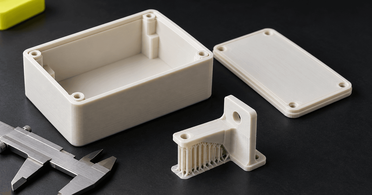
3D-printed parts can fail to fit because the design leaves too little clearance, the printed surfaces differ from the CAD dimensions, or the mating component is different from the one the model assumes. A gap that looks sufficient on screen can disappear once manufacturing variation and surface texture are involved. Start by defining how the assembly should work, then check the actual interface with a representative test fit.
A removable enclosure lid, a bracket around a tube and a sliding rail need different fits. Saying that two parts must fit together does not tell a supplier whether they should move freely, locate without much movement, or stay joined. That behaviour is part of the design requirement.
Decide what the fit needs to do
Describe the assembly in ordinary terms. Should the lid lift off by hand? Does the rail need to slide repeatedly? Is a fastener holding the parts, or does the joint itself provide retention? Include how often the assembly will be opened and which surfaces must remain accessible.
A clearance fit leaves space between mating surfaces. An interference fit deliberately overlaps their intended sizes so assembly depends on force or deformation. A fit intended to locate a component can fall between those cases. The appropriate choice depends on the part, material and assembly method; a tight-looking CAD model alone does not establish it.
Clearance and tolerance describe different things
Clearance is the designed space between parts. Tolerance is the permitted variation around a specified dimension. If a hole and a shaft have identical nominal diameters, the design has no planned gap between them. Manufacturing variation in either component can then prevent assembly, even when neither looks obviously distorted.
Be clear about where a gap is measured. For a centred round shaft inside a hole, the difference between their diameters spans both sides of the shaft. It is not the same as the gap on one side. For an enclosure, a gap between one pair of faces is different from a change to the lid's overall width. Mark the relevant surfaces rather than leaving the supplier to infer which interpretation you mean.
There is no single clearance value that works for every printed assembly. Process, geometry, orientation, material and the required movement all matter. Agree the fit and how it will be checked, especially where several interfaces must work together.
Look closely at holes, corners and contact surfaces
A nominally round hole is still made through a printing process. Its exported mesh, layer paths, surface texture and local geometry affect the usable opening. A hole may feel tight because of one rough region or a seam rather than because every part dimension is wrong. Square corners and small locating lips can similarly become the first contact points when a lid is fitted.
Identify where the parts catch. Does a lid sit correctly until one corner reaches the enclosure? Does a pin enter the hole but bind farther in? Does the assembly rock after fastening? Those observations help distinguish an opening-size issue from alignment, depth or a local obstruction.
Check file units and overall size before changing the design. If only one hole or lip is tight, globally enlarging or shrinking the model also changes hole spacing, wall sections and every other interface. A controlled change to the relevant feature is usually easier to evaluate than scaling the whole part as a guess.
Orientation and supports can change an interface
FDM, or fused deposition modelling, lays plastic filament in layers. Rotating a part changes how a hole, ledge or curved surface is built. A hole running through the layers has different preparation considerations from one whose upper surface forms an overhang. Supported faces may also retain contact marks that affect assembly.
Resin printing also has orientation and support-placement decisions, followed by cleaning and curing. Finer-looking layers do not automatically prove that a finished interface will fit. Tell the supplier which faces mate and whether support marks or finishing on those faces would matter.
A wider first-layer edge can be enough to cause binding
In filament printing, the first layer is pressed against the build surface. If material spreads at that edge, the base can be wider than intended. This is commonly called elephant's foot. A part can therefore measure or look acceptable above its base while still catching when that bottom edge enters a close-fitting opening.
Print preparation, first-layer control or a suitable edge chamfer can help address that local issue. A chamfer is a bevel along an edge. These choices need to suit the part and the profile; they are not a substitute for planned assembly clearance or a universal correction amount.
Consider material and finishing before judging the fit
Cooling, shrinkage and distortion can affect printed geometry. Material stiffness and flexibility also change how an assembly feels: a flexible component may deform during installation where a rigid one does not. That does not make either behaviour suitable without considering the purpose of the joint.
Support removal, sanding and resin post-curing can change a surface or dimension. Check the sample in its agreed finished state. If a one-off part has been hand-fitted, record what was changed before treating it as the reference for a repeat order. A new material, orientation or finish may need another fit review.
Measure the component the print will actually meet
For a replacement part, the existing component may not match its original drawing. Wear, damage, a coating or a previous alteration can affect the interface. Send available dimensions, photographs and drawings, and explain which measurements come from the actual item. Include both mating parts or files where possible.
An outer width alone may not explain an assembly. Hole positions, engagement depth, nearby corners, insertion direction and room for a fastener can all matter. Identify the faces used as measurement references so a dimension is not checked from a different edge on each revision.
Use a representative fit test before repeating the part
A small test section can be useful when it reproduces the relevant interface. It should retain the geometry, wall behaviour, material, orientation and finishing that influence the fit. A convenient flat sample does not necessarily answer a question about a supported hole or a flexible snap feature on the finished part.
- Define the intended fit and the actual mating component before preparing a test.
- Choose a representative section or prototype and record its file revision and production assumptions.
- Check the finished sample against the real component, including insertion, removal and any movement needed.
- Record where contact occurs and what needs changing; revise the relevant features deliberately.
- Retest the revised interface, then identify the accepted revision before requesting repeat parts.
A successful fit test answers the assembly question it was designed for. It does not by itself establish strength, wear life or performance in a different environment. Describe those requirements separately if they are part of the project.
For a BlackCoat enquiry, explain the assembly behaviour and send what you have. CAD support can help review the relevant geometry before a printing route and test approach are agreed. A clear fit requirement makes that discussion more useful than requesting a tighter print without identifying the interface.
Further reading
Next steps